Removing dissolved oxygen from water prevents oxidative spoilage, extends shelf life and reduces staling off-flavors when water contacts beer during transfers, filtration and filling. Modern deaeration solutions using CO₂ displacement, vacuum stripping or membrane technologies can routinely reach single-digit ppb DO under controlled conditions; many commercial modules target ≤10 ppb in cold water streams.
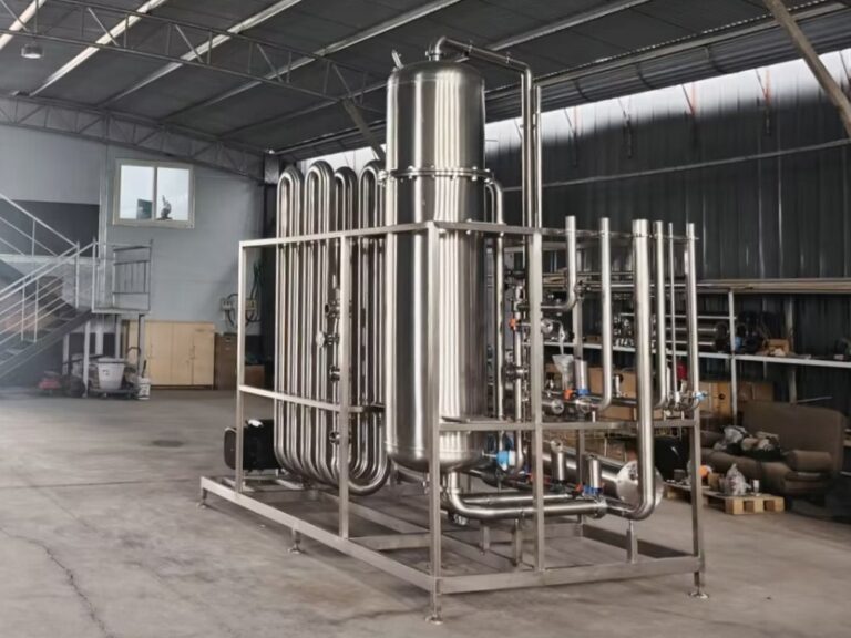
This system is built around a high-efficiency packed mass-transfer tower with an upstream flow-balancing module, downstream degassed-water storage tank, integrated cooling and an automated CO₂ replacement and mixing sequence. It’s engineered for brewery integration (RO/DI upstream, dosing, pump redundancy, PLC/SCADA connectivity) and designed for hygienic cleaning with automated CIP.
Process parameters
- Capacity (max flow): 5–120 m³/h (configurable by packing and tower diameter) — user specification.
- Target deoxygenation: dissolved O₂ ≤ 10 ppb (real-time monitoring via inline DO meter). Commercial modules and skids commonly guarantee ≤10 ppb under specified conditions.
- Degassed water temperature: typically 2–4 ℃ (cooler water increases O₂ solubility but allows better packaging control; many breweries operate cold deaeration or near-ambient depending on strategy).
Performance characteristics
- High mass-transfer efficiency: Structured or high-performance random packing maximizes gas-liquid contact area for rapid O₂ displacement with minimal CO₂ consumption.
- Integrated, platform-mounted piping: All process lines, valves and instruments are skid-mounted for a compact footprint and simplified installation; argon-arc welding and polished internals preserve hygiene.
- Automated control & monitoring: PLC sequences for evacuation/CO₂ replacement, CO₂ dosing and mixing, level control and CIP programs minimize operator intervention and ensure repeatable DO results.
Core subunits
- Front balance/flow stabilization unit: Keeps liquid flow and gas flow ratios steady so the water film distribution and CO₂ convection across packing remain stable — a prerequisite for repeatable DO removal.
- Mass transfer (packed) tower: Engineered packing and a flow distributor create a thin liquid film and a large interfacial area for efficient O₂ transfer to CO₂/stripping gas. Choose structured packing for lower pressure drop or high-efficiency random packing for fouling resistance.
- Level control unit: Automatic detection and PLC logic maintain correct liquid levels for different operation phases (evacuation, replacement, normal feed).
- Cooling unit: Plate heat exchanger and refrigeration loop hold a degassing loop at 2–4 ℃ where specified by the process design.
- CO₂ replacement & mixing unit: Pressure stabilizers, flow meters and pneumatic valves execute an evacuation and CO₂ purge according to programmable recipes to minimize residual oxygen quickly and reproducibly.
- CIP control unit: Automated CIP with a designed spray pattern and access points to remove scale and biofilms from packing and tower internals, essential because packed beds require specific cleaning strategies.
Technical specification
- Capacity: 5–120 m³/h
- Target DO (typ.): ≤ 10 ppb (dependent on feed water temperature and system sizing) — guarantee subject to quoted conditions.
- Degassing temp: 2–4 ℃ (adjustable)
- Packing: structured or high-efficiency random packing options
- Materials: 304SS standard; 316SS optional for aggressive chemistries
- Surface finish: polished internals; pickled & passivated
- Controls: PLC/HMI, CO₂ flow control, VFD pumps, DO meter, temperature and level sensors
- CIP: automatic program; dedicated ports and return manifold
Installation & operational notes
- For high-throughput plants, specify pump redundancy (N+1) and large-bore distribution manifolds to supply multiple packaging lines without pressure loss.
- Locate DO sensor after the degassing tower outlet and before the distribution headers; place sample ports for cross-checks.
- Provide CO₂ source (plant CO₂ recovery or cylinders/bulk) sized for peak demand and a pressure-stabilized supply skid with flow meters and safety interlocks. Integrating brewery CO₂ recovery systems reduces operating cost and carbon footprint.
- Plan CIP routing and drain capacity: packed towers can trap residues if CIP is under-designed — ensure return lines and acidic/alkaline CIP chemistries are specified.